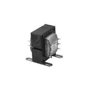
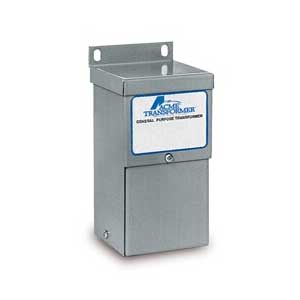
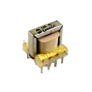
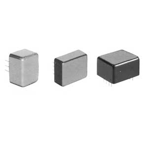
Each transformer has the winding arrangement and terminal numbering shown in the schematic diagrams. The primary windings may be used in series to raise or lower the secondary voltage output. A variety of combinations is possible using the taps on both windings for “Aiding” or “Bucking” action.
Designed for 117 V, 50/60 cycle operation; however, may be satisfactorily operated at 400 cycles.
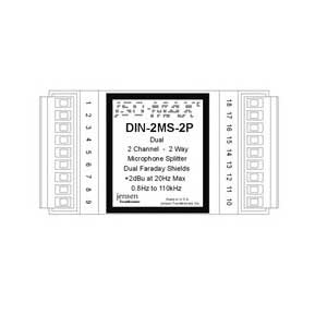
The secondary winding of each transformer consists of two identical windings connected to terminals 8 & 9 and to 10 & 11 respectively. Use the tables showing the various output voltages for specific terminal connections as your guide. Many combinations are possible other than those listed in the tables. All ratings shown are for normal convection air cooled applications.
| Mfr. Part No. | Description |
| RT-201 | Rectifier Circuit, C.T. Bridge |
| RT-202 | Rectifier Circuit, C.T. Bridge |
| RT-204 | Rectifier Circuit, C.T. Bridge |
| RT-206 | Rectifier Circuit, C.T. Bridge |
| RT-208 | Rectifier Circuit, C.T. Bridge |
| RT-402 | Rectifier Circuit, C.T. Bridge |


Phone : + 86-28-65770218
Fax : + 86-28-86129221
Email : sunny@asicedirect.com
And constantly improve our products and services to provide efficient custom automation solutions to ensure that customers get fast, professional service and support.
A solution provider in the industrial control & electronic market, providing quality automation parts.
Headquarters: ![]()
© 2015-2022 A&S Automation.,Ltd. All Rights Reserved.