Home Programmable Logic Controller (PLC) Fanuc IC655ALG516 PLC

Fanuc IC655ALG516 PLC

share
Fanuc IC655ALG516 PLC
Manufacturer: Fanuc

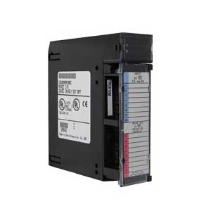
All unused inputs should be tied to the common connection (connect the +, -, and OV terminals together on all unused channels).

If the 24 VDC external supply is power cycled along with the Series 5 CPU/Analog module, glitches in analog input data may be present for a period of time. Do not cycle 24 VDC power if valid data is needed immediately after power-up. The time duration of these glitches depends on the power-up characteristics of the 24 VDC supply.

If frequent momentary power cycles are anticipated (e.g. off 1 second, then back on), then at least 1 second should lapse before accepting analog data as valid.
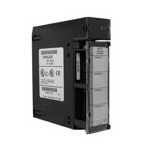
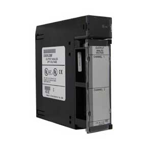
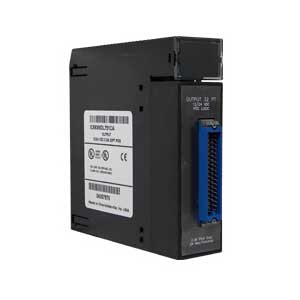
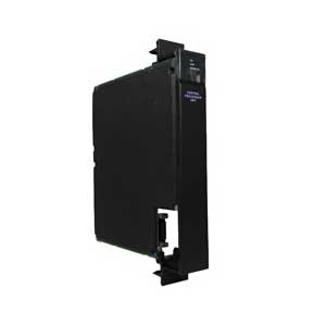
More+
Features Model
  • The Series Five 8 channel Analog Input module provides eight input channels, each capable of
  • converting an analog input signal to a digital signal for use as required by your application. Connections are provided at the 38 terminal removable terminal block for either voltage or current inputs. These inputs can be +1 to +5 V, 0 to +lO V, -10 to +lO V, or 4 to 20 mA. Resolution of the converted signal is 12 bits binary (1 part in 4096).
  • Three groups of LEDs provide a visual indication of module status. A 12.bit LED display provides a visual indication of the input data. The channel to be displayed is selected by successive depressions of a pushbutton switch on the front of the module. A group of eight LEDs indicates the selected channel and another group of eight shows the channel being scanned.
  • There are three other LEDs on the faceplate. GEN is on when the module address is mapped into either the Il+ or 12+ status table; DIAG when on, indicates that an internal failure has been detected by the module, and ADR, when on indicates that the 8 LEDs in the two columns to the right have been instructed by the CPU to display the module’s starting address in BCD format.
  • Inputs to the module can be either single ended or differential voltages or a current source. This module uses an integrating type converter for analog to digital conversion and the conversion time is selectable, either 10 ms or 100 ms. The integrating converter also provides immunity to noise spikes and has excellent 60 Hertz noise rejection. Isolation between user inputs and the base unit power supply is provided by opto-isolators on the module. An Analog Input module consumes 32 consecutive Input points. , beginning with the fast Input reference assigned to the slot in which the module is installed.
  • Input range, conversion time, and number of channels to be scanned are selected by configuration of a group of DIP switches and jumpers. Field wiring is made to the removable terminal block on the module.
Mfr. Part No. Description
IC655ALG516 Resolution, 12 Bit Binary (1 part in 4096)

Inquiry

Your Name: * name not null!
Email: * name not null!
Additional Information: * name not null!
Add more information ( Optional )
Code: *
click